

Before you start
- Having chosen compatible parts: see What each PC component does
- Keeping the motherboard manual to hand (paper or PDF)
In plain words
Building a PC is like assembling flat-pack furniture where every part is keyed: each plug only goes in one way and in one place. You need neither force nor soldering, just order, patience and the motherboard manual open beside you.
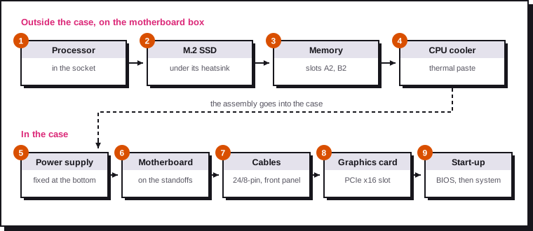
This tutorial follows the most practical order: you first equip the motherboard outside the case, where everything is accessible, then you install it in the case. Allow two to three hours for a first build.
1. Preparing the space and tools
The kit:
- A PH2 Phillips screwdriver (magnetic if possible), and a PH1 for the small M.2 screws.
- Cable ties or Velcro straps to tidy the cables.
- A lamp or a head torch: the inside of a case is dark.
- A small bowl for the screws.
- The motherboard manual, open at the "installation" and "internal connectors" pages.
The space: a clear, well-lit table, on a hard floor rather than carpet.
Static electricity
A static discharge can damage a component without you feeling it. Regularly touch an unpainted metal part of the case, or wear an antistatic wrist strap connected to the chassis. Handle boards by their edges, without touching the gold contacts or the pins.
Before you start:
- Unpack the parts and check the contents of each box (screws, cables, standoffs).
- Place the motherboard on its cardboard box, never on the antistatic bag: the outside of the bag can be conductive.
- Find in the manual the recommended memory slots and the pinout of the front panel connector.
2. Installing the processor
The processor is the most fragile part of the build. The pins are either on the motherboard (AM5 and LGA1851) or under the processor on older platforms: a bent pin can make the board unusable.
Step 1. Open the socket: press the metal lever, move it slightly to the side, then lift it. The retention frame rises.
Step 2. Find the gold triangle in one corner of the processor and the matching mark on the socket. The notches on the edges of the processor must line up with the socket's keys.
Step 3. Hold the processor by its edges and set it down flat, without sliding it. It should drop into place by itself, with no pressure.
Step 4. Lower the frame, then the lever, until it hooks under its catch. The resistance is normal and fairly strong.
Step 5. The plastic socket cover usually pops off by itself when you close the lever. Keep it: it's required for a motherboard warranty return.
Never force the processor
If the processor doesn't sit flat, remove it and check the orientation. Never push it in.
3. Installing the M.2 SSD
Step 1. Find the main M.2 slot in the manual (often the one closest to the processor, wired directly to it). Unscrew its heatsink if it has one.
Step 2. Remove the protective plastic film stuck to the heatsink's thermal pad. Forgetting this film is a common mistake: the SSD then runs much hotter.
Step 3. Insert the SSD at an angle, about 30°, into the connector. Lower it flat, then fix it with its screw or tool-free latch.
Step 4. Screw the heatsink back on.
Why the SSD before the CPU cooler
On many boards, the first M.2 slot sits under the CPU cooler or under the graphics card. Installing it first saves taking everything apart again.
4. Installing the memory
Step 1. Open the latches on the memory slots (on one side only on most recent boards).
Step 2. With two modules, use the slots shown in the manual, almost always A2 and B2 (the second and fourth counting from the processor).
Step 3. Line up the notch on the module with the key in the slot: it only goes in one way.
Step 4. Press firmly and vertically at both ends until the latch clicks. It takes more force than you'd think; a half-seated module is the number one cause of a PC that won't start.
5. Fitting the CPU cooler
Step 1. Fit the mounting hardware supplied with the cooler according to its instructions. On AM5, most coolers reuse the motherboard's original backplate: you just remove the two plastic clips.
Step 2. If the cooler doesn't have pre-applied thermal paste, put a pea-sized blob in the centre of the processor (or a thin cross on large processors). The cooler's pressure spreads it.
Step 3. Remove the plastic film under the cooler's base.
Step 4. Set the cooler down flat, then screw it in diagonally, a few turns at a time on each screw, until they stop.
Step 5. Plug the fan into the CPU_FAN header. For an AIO liquid cooler, the pump goes on AIO_PUMP (or CPU_FAN, depending on the manual) and the radiator is fixed in the case later.
Check access to the memory
A large cooler can cover the first memory slot. If the module sticks up too far, raise the cooler's fan a few millimetres on its heatsink.
6. Preparing the case and installing the power supply
Step 1. Remove both side panels and lay them flat, away from the work area (especially tempered glass).
Step 2. Check the standoffs (small threaded posts): they must match the motherboard's holes exactly. An extra standoff under the board can cause a short circuit.
Step 3. If the motherboard doesn't have a built-in rear plate, clip the I/O shield into the case, from the inside, before installing the board.
Step 4. Install the power supply in its compartment, usually at the bottom. If the case has a filtered vent under the power supply, point its fan downwards; otherwise, inwards.
Step 5. With a modular power supply, connect the cables you need now: 24-pin ATX, 8-pin EPS, PCIe or 12V-2x6 for the graphics card, SATA if needed. Route them through the grommets towards the front of the motherboard.
7. Installing the motherboard
Step 1. Tilt the motherboard to engage the rear ports in their opening first, then lay it on the standoffs.
Step 2. Check that all the holes line up with the standoffs.
Step 3. Screw it in without forcing, starting with the central screw, which often acts as a guide, then the others diagonally.
Step 4. If you have an AIO liquid cooler, now fix its radiator (at the front or top), then the pump on the processor, as described in step 5.
8. Connecting the cables
The motherboard's two power cables:
- 24-pin ATX: on the right-hand side of the board. It takes firm pressure until the clip clicks.
- 8-pin EPS (4+4): at the top left, near the processor. Some boards have a second 4- or 8-pin connector: it's mainly useful for powerful processors, so check the manual. Don't confuse it with an 8-pin PCIe cable: the two look alike but aren't interchangeable.
The front panel connector (F_PANEL) links the power button, the reset button and the case LEDs. It's the trickiest step, because the wires are separate and tiny.
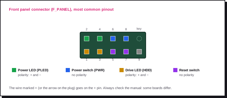
- The buttons (POWER SW, RESET SW) have no polarity: connect them either way round.
- The LEDs (POWER LED, HDD LED) do have a polarity: the wire marked + goes on the + pin. Reversed, the LED doesn't light up, with no danger.
- Some boards come with a small adapter onto which you plug the wires before fitting it in one go.
The other case connectors:
| Case cable | Motherboard header | Note |
|---|---|---|
| USB 3 (thick blue cable, 19 pins) | USB3 / USB 5 Gbit/s | Fragile pins: line it up carefully before pressing |
| USB-C (small flat connector) | USB 3.2 Gen 2 or Gen 2x2 (Type-E) | Clips in one way only, without forcing |
| HD AUDIO | AAFP / HD_AUDIO | Usually at the bottom left of the board |
| Fans | CPU_FAN, SYS_FAN, CHA_FAN | Or on the case's hub, itself connected to a SYS_FAN |
| 2.5" SSD or hard drive | SATA (data) + SATA power cable | Not needed for M.2 SSDs |
9. Installing the graphics card
Skip this step if you're using the processor's integrated graphics.
Step 1. Remove the metal covers at the back of the case, opposite the first PCIe x16 slot (often two or three covers for a thick card).
Step 2. Open the PCIe slot latch. Line up the card and push it in vertically until the latch clicks.
Step 3. Screw its bracket to the case.
Step 4. Connect the card's power:
- 12V-2x6 connector (16 pins): push it in all the way, with no visible gap between the plug and the socket. Don't bend the cable right at the plug; leave a few centimetres straight before any curve.
- 8-pin PCIe connectors: use a separate cable for each connector when the power supply allows, rather than a single cable with two daisy-chained plugs.
Step 5. If the card is long and heavy, fit the anti-sag bracket often supplied with the card or the case.
10. Organising airflow and cables
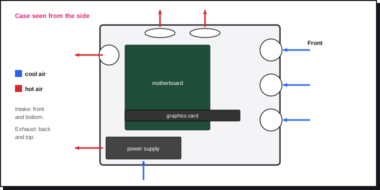
- Fans blow out on the side opposite their visible blades, in the direction of the arrow moulded on their frame.
- Aim for slightly more intake than exhaust: dust then mostly comes in through the filters.
- Tidy the cables behind the motherboard tray with ties. Nothing must touch a fan's blades.
11. First start-up
Step 1. Before closing the case, do a visual check:
| Item | Done? |
|---|---|
| 24-pin ATX and 8-pin EPS connected until they click | ☐ |
| Memory modules pushed in, latches closed | ☐ |
| Processor fan on CPU_FAN | ☐ |
| Graphics card powered, 12V-2x6 pushed all the way in | ☐ |
| No screws or tools left in the case | ☐ |
| Monitor connected to the graphics card (or to the motherboard without a graphics card) | ☐ |
Step 2. Plug in the mains cable, flip the power supply switch to I, then press the power button.
Step 3. Be patient. At the very first start-up, the motherboard calibrates the DDR5 memory (memory training). The screen may stay black for several minutes, or even restart once or twice. This is normal: don't switch off during this time.
Step 4. If nothing appears after 5 minutes, look at the motherboard's diagnostic LEDs (CPU, DRAM, VGA, BOOT): the one that stays lit points to the part at fault. The page PC won't start explains the rest of the diagnosis.
Close the case after the test
Leave the side panel open until the first successful start-up. If a cable is badly connected, it's still accessible.
12. Setting up the BIOS
Enter the BIOS (UEFI) by pressing Delete or F2 during start-up.
Step 1. Check that everything is detected: processor model, total amount of memory, SSD.
Step 2. Check the processor's idle temperature: it should be reasonable (generally between 30 and 50 °C). A temperature that climbs quickly signals a badly tightened cooler or a forgotten plastic film.
Step 3. Turn on the EXPO (AMD) or XMP (Intel) memory profile so the memory runs at its rated speed. Save and restart: a new memory calibration may take place.
Step 4. Update the BIOS with the built-in tool (often EZ Flash, Q-Flash or M-Flash depending on the manufacturer) and a file downloaded from the manufacturer's website, copied to a FAT32 USB stick. Never cut the power during the update.
Step 5. Turn on the TPM (fTPM on AMD, PTT on Intel), required by Windows 11, and leave start-up in UEFI mode with Secure Boot on: Windows 11 requires a Secure Boot-capable PC, and turning it on protects against malware that loads before the system.
Step 6. Set the boot order to the installation USB stick, then install the system.
13. After installing the system
- Install the chipset and network drivers from the motherboard manufacturer's website, then the graphics driver from the Nvidia, AMD or Intel website.
- Check in Task Manager (or with
free -hon Linux) that all the memory is available and that its speed matches the profile turned on. - Run a load test for a few minutes (a render, a game, a stability test tool) while watching the temperatures.
- Close the case, then note in a file the list of components, the BIOS version and the build date: useful for a future upgrade or a warranty claim.
| Problem after the build | Most likely cause |
|---|---|
| Nothing lights up | Power supply switch on O, POWER SW cable in the wrong place |
| Fans spin, black screen | Memory calibration in progress, module not fully seated, monitor plugged into the motherboard instead of the graphics card |
| Only half the memory shown | One module not fully seated or in the wrong slot |
| Very hot processor | Cooler's plastic film left on, cooler badly tightened, no paste |
| "CPU fan error" message | Fan connected somewhere other than CPU_FAN |
| Front panel button or front USB does nothing | Front panel connector or internal USB badly connected |